The ease of this purchase was a good start. The content of this manual was exactly all I needed to retore my Tandberg 64.
All of the mechanical and electrical information is contained in the manual and the quality of the document makes reading the data easy.
The exerience with the resource has made this my prime source for technical data.
Owner-manuals.com is the best Possibility to give vantage HIGH CLASS Elektronic COMPONENTS
a new Life.Thanks alot for your perfekt Service.
Text excerpt from page 4 (click to view)
RX-5020VBK/RX5022VSL
Disassembly method
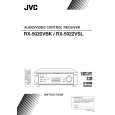
Removing the top cover (See Fig.1)
1. Remove the four screws A attaching the top cover on both sides of the body. 2. Remove the three screws B on the back of the body. 3. Remove the top cover from behind in the direction of the arrow while pulling both sides outward.
Top cover
B
A
2
A
2
Fig.1
Front panel assembly
Removing the front panel assembly (See Fig.2 and 3)
Prior to performing the following procedure, remove the top cover. 1. Disconnect the card wire from connector CN402 on the audio board and CN201 on the power supply board in the front panel assembly. 2. Cut off the tie band fixing the harness. 3. Remove the three screws C panel assembly. attaching the front
C
Tie band
C
CN201
Main board CN402 Power supply board
Audio board
Fig.2
Front panel assembly
4. Remove the four screws D attaching the front panel assembly on the bottom of the body. Detach the front panel assembly toward the front.
D
D
Removing the rear panel
(See Fig.4)
Prior to performing the following procedure, remove the top cover. 1. Remove the power cord stopper from the rear panel by moving it in the direction of the arrow. 2. Remove the seventeen screws E attaching the audio input board, DVD board, video board and tuner board to the rear panel on the back of the body. 3. Remove the four screws F attaching the rear panel on the back of the body. Fig.3