|
|
|
Who's Online
There currently are 5977 guests online. |
|
Categories
|
|
Information
|
|
Featured Product
|
|
|
 |
|
|
There are currently no product reviews.
 ;
hello this Service Manual PIONER KXE60 is very good, thanks.
 ;
It was just what I needed. Thanks for your quick action and great price. You guys are top notch.
Thanks
;
Excellent manual, complete, great resolution, easy to read especially the schematics. Thank you !
;
Fast delivery, excellent resolution and complete. And above all, the best price ever !
;
Vielen Dank,
das war eine prima Sache. Habe das Serviceheft nach 3 Stunden herunterladen können. Qualität OK. Hat mir mit Erfolg bei der Fehlersuche und Reparatur meines
Nordmende Galaxy Mesa 9000 geholfen. Ich kann diesen Service bestens weiterempfehlen
A very good service.
Thank You!
RX-5032VSL
2.7 Removing the speaker terminal board (See Fig.8) � Prior to performing the following procedure, remove the top cover and rear panel. (1) From the top side of the main body, remove the solders from the soldered sections a on the speaker terminal board.
Parallel wires
Soldered sections a Speaker terminal board Fig.8
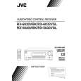
2.8 Removing the main board (See Fig.9) � Prior to performing the following procedure, remove the top cover. (1) From the top side of the main body, remove the tie bands fixing the wires. (2) Remove the tie band and wire protection board fixing the card wire. (3) Remove the solders from the soldered section b on the (4) (5) (6) (7) (8) (9) speaker terminal board attaching the parallel wires. Disconnect the relay board from the connectors (CN291, CN491) on the power supply board and audio board. Disconnect the parallel wire from the connector CN241 on the power supply board. Disconnect the wire from the connector CN251 on the power transformer board 1. Disconnect the wires from the connectors CN471, CN472 and CN473 on the audio board. Remove the screw H, two screws J and four screws K attaching the main board. Take out the main board.
Relay board Tie bands K Main board K Tie band Tie band Wire protection board CN251 CN291 Power transformer board 1 Power supply board CN241
K
J
Card wire CN473
Power transformer
H
CN472 Audio Parallel wires board CN471 CN491 Speaker terminal board Soldered section b
Fig.9
(No.22028)1-7
|
|
|
> |
|