|
|
|
Who's Online
There currently are 6042 guests online. |
|
Categories
|
|
Information
|
|
Featured Product
|
|
|
 |
|
|
There are currently no product reviews.
 ;
Excellent service manual, the only known point of note is the alignment of improvability scanned pages within the pdf page. The resolution is good.
;
I was very glad recieving the service manal from You. Additionaly very fast. Extremaly nice servicing. Thanks very mach! Now my GX-220 working better, than it was made. Alexander from Moscow, Russia/
;
Sweet! I won the item on eBay and couldn't adjust the geometry or even keep a steady picure. This guide has the full schematics (not available anywhere else as far as I could tell), and was a bargain for the wealth of knowledge it contains. I hooked it up to my testing equipment, tweaked a few potentiometers and got it playing videogames in no time. Thanks!
;
It was just what I need to fix my old BMW's CD player. Very convenient also. Thank you.
;
Great Manual! It contains all the wiring schematics and mechanical exploded views that are essential for service and repair. I was surprised I even found this for such an old machine. Only wish I knew of this site many years ago.
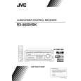
RX-8020VBK
Removing the power transformer (See Fig.17)
Prior to performing the following procedures, remove the top cover. 1. Disconnect the harness from the connector CN55 /CN56 and CN811 on the power trans1 board.
CN55/CN56 Power supply board
Power trans1 board
2. Unsolder the seven solder parts on the power trans2 board. 3. Remove the four screws U attaching the power transformer.
CN811
Removing the voltage selector board (See Fig.17)
Prior to performing the following procedure, remove the top cover.
U
Power transformer Power trans2 board
1. Removed the two screws G attaching the voltage selector board to the rear panel (see fig.4).
Solder part
2. Unsolder the six solder parts on the voltage selector board.
Voltage selector board
Removing the power/fuse board (See Fig.17)
Prior to performing the following procedure, remove the top cover. 1. Removed the two screws G attaching the voltage selector board to the rear panel (see fig.4).
Power cord Power/fuse board
(on the reverse side)
Solder part
2. Remove the screw H attaching the power/fuse board to the rear panel (see fig.4). 3. Remove the screw V attaching the power/fuse board. 4. Unsolder the eight solder parts on the power/fuse board.
Solder part
(on the reverse side)
V
Solder part
Removing the power supply board (See Fig.18)
Prior to performing the following procedure, remove the top cover and relay board. 1. Cut off the tie band if needed. 2. Disconnect the card wire from the connector CN402 on the power supply board. 3. Disconnect the harness from the connector CN55/CN56 on the power trans1 board (see fig.17). 4. Remove the three screws W attaching the power supply board and pull out the power supply board removing the hook.
Headphone jack board Power supply board
Headphone jack
W
CN402
W
(on the reverse side)
Solder part Hook Tie band
W
Tie band
5. Unsolder the three solder parts on the power supply board.
Fig.18
Under this board
Fig.17
1-7
|
|
|
> |
|