|
|
|
Who's Online
There currently are 5964 guests online. |
|
Categories
|
|
Information
|
|
Featured Product
|
|
|
 |
|
|
There are currently no product reviews.
 ;
El producto satisface las necesidades del servicio t
;
This is a good quality scan of the Operation & Maintenance (Service) Manual for the PAL version of this high-band broadcast umatic, BVU-800P
All schematics and lineup procedures appear to be included in this one manual AFAICT.
The file size is just over 113 MB which gives an idea of the quality and number of pages.
All of the schematics, which contain some fairly small print, are easily readable when you zoom into the page.
John Thompson, Newcastle Upon Tyne, England.
;
Good quality, all schematics of few of models. There is also short form of user manual and regulation manual.
;
Perfect copy of the service manual. you can enlarge every page, and it comes up
with all details.
;
It´s very very nice manual with all, what i need. Original in good quality. Very fast business. Very much thanks...
RX-8022PSL
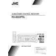
Removing the main board (See Fig.13 to 15)
Prior to performing the following procedure, remove the top cover.
Tie band
M
CN721 CN723
Tie band
M
1. Remove the card wire and cut off the tie bands.
Card wire
2. Disconnect the harness from the connector CN721, L CN723, CN813, CN814, CN831 and CN881 on the main board. Main board 3. Disconnect the harness from the connector CN722 on the Cch amp. board (see fig.5). 4. Disconnect the harness from the connector CN811 on the power trans1 board. 6. Remove the screw K, after removing the relay board if needed (see fig.11). 7. Remove the two screws L and the six screws M attaching the main board. 8. Remove the two screws N attaching the heat sink to the main board. 9. Disconnect the connector of each amp. board.
CN831 CN814 CN813
CN811 Power trans1 board CN722
K
L
CN881
Fig.13
Heat sink
N
Main board (reverse side)
Fig.14
Rch amp. board Lch amp. board Cch amp. board
Removing the each amp. board of Cch, Lch, Rch, RLch and RRch (See Fig.16)
Prior to performing the following procedure, remove the top cover and main board.
RLch amp. board RRch amp. board
Heat sink
Main board
1. Remove the two screws O attaching the Cch amp. board and remove the Cch amp. board. 2. Remove the two screws P attaching the Lch amp. board and remove the Lch amp. board. 3. Remove the two screws Q attaching the Rch amp. board and remove the Rch amp. board. 4. Remove the two screws R attaching the RLch amp. board and remove the SLch amp. board. 5. Remove the two screws S attaching the RRch amp. board and remove the SRch amp. board.
CN706 CN705 CN702 CN701 CN703
Fig.15
S(RRch)
Q(Rch)
Heat sink
O(Cch)
Removing the Heat sink
(See Fig.16)
T
T
Prior to performing the following procedure, remove the top cover, main board and each amp. board. 1. Remove the four screws T attaching the two brackets to the heat sink and remove the two brackets. 1-6
Bracket
R(RLch)
Fig.16
P(Lch)
Bracket
|
|
|
> |
|