|
|
|
Who's Online
There currently are 5931 guests online. |
|
Categories
|
|
Information
|
|
Featured Product
|
|
|
 |
|
|
There are currently no product reviews.
 ;
Very fast, clear and usefull site !
Also this Service Manual are very well maked and with a very good definition !
Very fast download speed !
Recomended Seller !
;
The manual you sent me was excellent. It included clear, readable diagrams and a usable parts list. I would surely use your service again. Thanks
;
Payments were processed quickly and items were exactly as described. I will use owner-manuals.com in the future for any other manual needs.
;
The Technics manual was very clear and I was able to solve my technical problems.
I did not think that anyone kept these manuals and was pleasantly surprised to find them on the Internet and at an affordable price.
I would recommend Owner Manuals as a first source of technical products for ‘dated’ equipment manuals.
Ian
;
The content of the manual was not found on the Internet and was a hard find. I check the net for 5 hours until I came across this web-site. When I did find the book it Auto loaded into my IPAD PDF shelf for books for review at anytime. Overall I am satisfied with the book and it answered all my questions. This repair book is obsolete because the product I bout it for is pretty old. Thanks for the help with the download and even having the manual. Thanks 73's K5HRD
RX-DV3SL
Disassembly method
Removing the top cover (See Fig.1)
1. Remove the four screws marked A attaching the top cover on both sides of the body. 2. Remove the three screws marked B on the back of the body. 3. Remove the top cover from behind in the direction of
Top cover
B
A
2
A
2
Fig.1
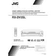
Front panel assembly
Removing the front panel assembly (See Fig.2 to 4)
Prior to performing the following procedures, remove the top cover. 1. Disconnect the card wire from the connector CN114 on the main board. 2. Remove the five screws marked C attaching the front panel assembly on the bottom of the body. Detach the front panel assembly toward the front. 3. Release the two joints marked a on both sides on the bottom of the body using a screwdriver.
Tie band Power supply board
CN114 Main board Amplifier board
CN201 DSP board
Power /Fuse board
Fig.2
Front panel assembly
C
C
Joint a
Fig.4 Fig.3
Removing the rear panel
(See Fig.5)
Cord stopper Rear panel
Prior to performing the following procedures, remove the top cover. 1. Remove the power cord stopper from the rear panel by moving it in the direction of the arrow. 2. Remove the twenty one screws marked D attaching each boards to the rear panel on the back of the body. 3. Remove the three screws marked E attaching the rear panel on the back of the body.
D
D
E
DE
Fig.5
D
E
1-5
 $4.99 RX-DV3SL JVC
Owner's Manual Complete owner's manual in digital format. The manual will be available for download as PDF file aft…
|
|
|
> |
|