|
|
|
Who's Online
There currently are 6043 guests online. |
|
Categories
|
|
Information
|
|
Featured Product
|
|
|
 |
|
|
There are currently no product reviews.
 ;
The service manual is really great - thanks to it I was able to install the laser unit and thus "save" my CD-player, which seemed to be impossible before I had the manual.
;
Downloaded the Service manual OK of the Technics Piano and have now repaired it and its going fine. Excellant; thank you for the fine servce. A.M
 ;
This site is working fine! Did buy a manual for SX-EX25L and after a while I could download it and fix the problem. Nice and easy!
;
Complete manual as pdf-file in very good quality. Very helpful and fast availability.
;
Complete service manual in very good scanning quality with all schematic and PWB graphics as well as assembly & maintenance instructions. A slight drawback is that the rastering of the PWB graphics sometimes makes it a bit difficult to follow fine traces, but no showstopper.
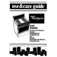
RX-E100RSL/RX-E100RSB Removing the audio board (See Fig.8)
CN515 power supply board Main board CN517 CN516
Prior to performing the following procedure, remove the top cover , the rear panel and the each board. 1. Disconnect the card wire from connector CN411 on the audio board. 2. Disconnect the harness from connector CN205 on the audio board. 3. Disconnect the harness from connector CN515, CN516, and CN517on the main board. 4. Remove the harness band fixing the harness. 5. Remove the three screws G board assembly. attaching the audio
CN411
G
Power transformer
Audio board
Harness band
CN205
Power / Fuse board
Fig.8
H H I I H
Main board
Removing the main board
(See Fig.9)
CN707 CN206
Prior to performing the following procedure, remove the top cover, the rear panel and audio board. 1. Remove the harness band fixing the harness. 2. Disconnect the harness from connector CN707 on the power supply board . 3. Disconnect the harness from connector CN202 and CN206 on the main board . 4. Remove the five screws H and the two screws I attaching the main board.
CN202 Harness band
H
Fig.9
J
Removing the Heat sink (See Fig.10 to 11)
1. Remove the ten screws K and four screws L attaching the heat sink. 2. Remove the two screws J attaching the heat sink from the rear side of main board.
Main board rear side Heat sink
J
Fig.10
K
K
K L
L
Fig.11
1-5
|
|
|
> |
|