|
|
|
Who's Online
There currently are 5916 guests online. |
|
Categories
|
|
Information
|
|
Featured Product
|
|
|
 |
|
|
There are currently no product reviews.
 ;
the manual is in good quality and it's in pdf. manual was send in less then 24h.
regards
mike
;
I would not plug this machine in without finding a manual like this. In addition to setup and normal operating instructions, it has troubleshooting flowcharts, diagrammed mechanical adjustments, and schematics to beat the band. The tech I hand it to would be thrilled to find solder side PCB diagrams with component outlines superimposed, pinouts for every IC chip, and line drawings of transistors, with labeled legs.
As for printing quality, this may be a copy of a copy, but even the finest print when enlarged is very legible. There is a bit of grayed print over a few pages, as if a wet page were placed over it, but the print is still very legible. If you could borrow an original manual and get it printed and bound for 4 to 6 times the cost, you could get better quality. In that case you wouldn't be here. For price, utility, and availability I am rating this manual highly.
;
I received the Manual in a timely manner and it was exactly what I needed.
This is a perfect copy of the Service Manual, The quality is great. I am very
happy. Thank you
;
exactly as they say. Within 24 hours the link to the pages and offcourse it was the right service manual. Super and thanks
 ;
The manual was exact the thing that was promised. My old car stereo is working again thanks to the information supplied.
TH-A30
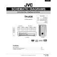
Removing the DSP board
(See Fig.9)
Prior to performing the following procedure, remove the top cover, front panel assembly, DVD mechanism assembly and jack board. 1. Remove the harness band fixing the harness. 2. Disconnect the harness from the connector J9 and J10 on the DSP board. 3. Disconnect the card wire from the connector J1 and J3 on the DSP board. 4. Remove the one screw L attaching the DSP board. 5. Remove the screw M1 and remove the earth wire. 6. Remove the one screw I attaching the DSP board to the rear panel (see fig.7). 7. Pull up the DSP board from the front side upwards disconnecting the connector J2, J5, J6 and J7.
Harness band DSP board
J3 J1
J10 J9
L
J6
J5 J7
J2
(fixing the earth wire)
M1
Fig.9
Main board
M2
Removing the main board
(See Fig.10)
Prior to performing the following procedure, remove the top cover, front panel assembly, power cord, DVD mechanism assembly, jack board and DSP board. ACW2 1. Disconnect the card wire from the connector CW8 on the main board. 2. Disconnect the harness from the connector ACW2, ACW3, ACW4 and ACW5 on the main board. 3. Remove the five screws J attaching the speaker terminals and jack to the rear panel (see fig.7). 4. Remove the nine screws M2 attaching the main board. 5. When the rear panel is not removed, pull up the main board from front side.
CW8
(Rear panel side)
Heat sink1
M2
Heat sink2 ACW3
M2
M2
Heat sink3
Fig.10
Solder part 1 (Each power transistor is fixed)
ACW5 ACW4
Main board (Reverse side )
Removing the power transistor & power IC (See Fig.10 to 12)
Prior to performing the following procedure, remove the top cover, front panel assembly, DVD mechanism assembly, jack board, DSP board and main board. 1. After removing the solder part 1 soldered to the main board, remove each screw and remove the heat sink from the power transistor. 2. After removing the solder part 2 soldered to the main board, remove each screw and remove the heat sink from the power IC.
Solder part 3 (Power IC is fixed) Solder part 2 (Power IC is fixed)
Fig.11
1-7
(Front panel side)
 $4.99 TH-A30 JVC
Circuit Diagrams Set of circuit diagrams. The diagrams will be provided as PDF file. The file will be delivered after… 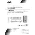 $4.99 TH-A30 JVC
Owner's Manual Complete owner's manual in digital format. The manual will be available for download as PDF file aft… 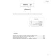 $4.99 TH-A30 JVC
Parts Catalog Parts Catalog only. It's available in PDF format. Useful, if Your equipment is broken and You need t…
|
|
|
> |
|