|
|
|
Who's Online
There currently are 5763 guests online. |
|
Categories
|
|
Information
|
|
Featured Product
|
|
|
 |
|
|
There are currently no product reviews.
 ;
A site where discontinualed schematic diagrams and back dated information can be found on discontinued radios tv's and any electronic equipment can be found. Newer manuals either Service and operating manuals. Radio amateurs should find this site a great source for ham radio equipment manuals. I will return to this site should I need information on any electrical equipment. priced easy to download in a PDF format and print pages need to undertake the repair.
;
Quality scan of the original. All the detail necessary to troubleshoot, repair and adjust the unit. I'm sure I will be downloading more manuals in the future as the need arises.
;
Exactly as described, a Service Manual complete with the schematics and PCB layout delivered in a timely manner. Many thanks for the great service.
 ;
some of the writing is a bit blur but the part in the schmatic was great and i have fixed the machine thanks
;
Well.. I'd searched for this manual and although I found many copies online I was pleased to find your website with a well balanced pricing system and easy to search and follow links. That together with the very quick response time was just what I was looking for.. being a very impatient tech.. ;-) I had the service manual in front of me within a short time.
Bookmarked.. and you can bet I will always come here first for my service & user manuals..
best regards
Ed(Tony) Foley
G7WHK
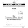
3.1.6 Removing the DSP board (See Figs.9 and 10) � Prior to performing the following procedures, remove the top panel and rear cover. (1) From the top side of the DSP board, disconnect the card wires from the connectors CN401 on the DSP board. (See Fig.10) (2) Remove the screw K attaching the DSP board from the section d of the barrier. (See Fig.10) (3) From the back side of the main body, remove the screw L and two screws M attaching the DSP board. (See Fig.9) Reference: � When attaching the DSP board, hang the DSP board on the section d of the barrier. (See Fig.10)
L
M
N
Fig.9
Rear panel
Section d
3.1.7 Removing the tuner (See Figs.9 and 11) � Prior to performing the following procedures, remove the top panel, rear cover and DSP board. (1) From the top side of the tuner, disconnect the card wire from the connector CN1 on the tuner. (See Fig.11) (2) From the back side of the main body, remove the two screws N attaching the tuner. (See Fig.9) (3) Take out the tuner from the main body.
K
CN401
DSP board
Fig.10
Tuner
Fig.11
CN1
(No.MB055)1-9
 $4.99 TH-A55 JVC
Circuit Diagrams Set of circuit diagrams. The diagrams will be provided as PDF file. The file will be delivered after… 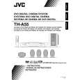 $4.99 TH-A55 JVC
Owner's Manual Complete owner's manual in digital format. The manual will be available for download as PDF file aft…  $4.99 TH-A55 JVC
Parts Catalog Parts Catalog only. It's available in PDF format. Useful, if Your equipment is broken and You need t…
|
|
|
> |
|