|
|
|
Who's Online
There currently are 6043 guests online. |
|
Categories
|
|
Information
|
|
Featured Product
|
|
|
 |
|
|
There are currently no product reviews.
 ;
El producto satisface las necesidades del servicio t
;
This is a good quality scan of the Operation & Maintenance (Service) Manual for the PAL version of this high-band broadcast umatic, BVU-800P
All schematics and lineup procedures appear to be included in this one manual AFAICT.
The file size is just over 113 MB which gives an idea of the quality and number of pages.
All of the schematics, which contain some fairly small print, are easily readable when you zoom into the page.
John Thompson, Newcastle Upon Tyne, England.
;
Good quality, all schematics of few of models. There is also short form of user manual and regulation manual.
;
Perfect copy of the service manual. you can enlarge every page, and it comes up
with all details.
;
It´s very very nice manual with all, what i need. Original in good quality. Very fast business. Very much thanks...
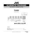
3.1.9 Removing the connect board (See Fig.14) � Remove the metal cover. � Remove the front panel assembly. (1) From the inside of the front panel assembly, disconnect the card wire from the connector CN561 on the connect board. (2) Remove the screw V attaching the support board. (3) Take out the connect board. 3.1.10 Removing the phone jack board (See Fig.14) � Remove the metal cover. � Remove the front panel assembly. (1) From the inside of the front panel assembly, remove the two screws W attaching the phone jack board. (2) Take out the phone jack board.
Phone jack board
W
CN561
Connect board
W V
Card wire
Support board
Fig.14
3.1.11 Removing the operation board (See Fig.15) � Remove the metal cover. � Remove the front panel assembly. � Remove the support board. (1) Remove the two screws X attaching the operation board. (2) Take out the operation board together the Button(top). Reference: Remove the Button(top) from the front board as required. 3.1.12 Removing the front board (See Figs.15 and 16) � Remove the metal cover. � Remove the front panel assembly. � Remove the connect board. � Remove the operation board. (1) From the front side of the front panel assembly, pull out the volume knob. (See Fig.16.) (2) Remove the screw Y attaching the front board. (See Fig.16.) (3) From the inside of the front panel assembly, remove the eight screws Z attaching the front board. (See Fig.15.) (4) Take out the front board while releasing the claws e in the direction of the arrow. (See Fig.15.)
Front board
X Z
Operation board Button(top)
Z
Claws e
Fig.15
Z
Front panel assembly
Y
Volme knob
Fig.16
(No.MB033)1-13
 $4.99 TH-M45 JVC
Circuit Diagrams Set of circuit diagrams. The diagrams will be provided as PDF file. The file will be delivered after… 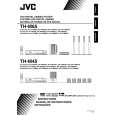 $4.99 TH-M45 JVC
Owner's Manual Complete owner's manual in digital format. The manual will be available for download as PDF file aft…  $4.99 TH-M45 JVC
Parts Catalog Parts Catalog only. It's available in PDF format. Useful, if Your equipment is broken and You need t…
|
|
|
> |
|