|
|
|
Who's Online
There currently are 5866 guests online. |
|
Categories
|
|
Information
|
|
Featured Product
|
|
|
 |
|
|
There are currently no product reviews.
 ;
Excellent printing quality. A complete and very useful manual with all details.
;
Even if the PDF is a scan, I can read the information I need.
The price is affordable and the service (mail sending) is very fast.
Thanks ! Regards. William (Fan of Kenwood)
;
Very good quality original datasheet!I like this amazing website!!!!!!
 ;
Excellent just what I needed to replace the electrolytic caps and make this old gem a beauty again. Was as scan of the original photocopied service manual.
;
It was helpful to get schematic with waveforms in important points and lot of service information. Manual is good quality, fast delivered. Of course it is hardcopy of paper one with all its disadvantages.
3.4.2 Removing the rear panel (See Figs.3 and 4) � Prior to performing the following procedure, remove the amplifier assembly. (1) From the back side of the amplifier assembly, remove the five screws C, screw D and screw E attaching the rear panel. (See Fig.4) (2) From the top side of the amplifier assembly, take out the rear panel with fan motor, and disconnect the wire from the connector CN202 on the amplifier board. (See Fig.3) 3.4.3 Removing the fan motor (See Fig.4) � Prior to performing the following procedures, remove the amplifier assembly and rear panel. (1) From the front side of the rear panel, remove the four screws F attaching the fan motor. (2) Take out the fan motor.
F
F
C
D
3.4.4 Removing the heat sink bracket (See Fig.5) � Prior to performing the following procedure, remove the amplifier assembly. (1) From the top side of the amplifier assembly, remove the three screws G and three screws H attaching the heat sink bracket. (2) Take out the heat sink bracket. Reference: When attaching the heat sink bracket, attach the screw H with barrier.
E
C
Fig.4
Amplifier assembly
H
Barrier
Heat sink bracket
Fig.5 3.4.5 Removing the amplifier board (See Fig.6) � Prior to performing the following procedures, remove the amplifier assembly and heat sink bracket. (1) From the top side of the amplifier assembly, disconnect the amplifier board from the connectors CN201 and CN203 on the main board. (2) Take out the amplifier board and disconnect the wire from the connector CN202 on the amplifier board.
G
CN202 Main board
CN203
Fig.6
CN201 Amplifier board
(No.MB198)1-27
 $4.99 TH-M606 JVC
Owner's Manual Complete owner's manual in digital format. The manual will be available for download as PDF file aft… 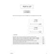 $4.99 TH-M606 JVC
Parts Catalog Parts Catalog only. It's available in PDF format. Useful, if Your equipment is broken and You need t…
|
|
|
> |
|