|
|
|
Who's Online
There currently are 6043 guests online. |
|
Categories
|
|
Information
|
|
Featured Product
|
|
|
 |
|
|
There are currently no product reviews.
 ;
good scans, all is clear. all pages in order. recommended
 ;
Très-très bon site, facile, très bon prix.
Au futur besoin, je n’hésiterais à faire appel à vous.
Merci
;
This is the correct service manual of SHARP RX-100H(BK) DAT.
;
The ervice manual for my 1982 Kenwood KR-1000 receiver is great! Full detail on all circuits with part number detail. I will definately be ordering more manuals for my other vintage equipment! Order was fulfilled quickly! Very efficient ordering process! Thnaks for your help! Great site!
;
Everything in the manual was excellent except for a couple of pictures of specific areas in the unit that were a little dark. Owners Manuals re-sent the pdf file & the problem was corrected. Excellent product! George
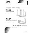
3.3.6 Removing the amp. board (See Fig.10) � Prior to performing the following procedures, remove the amplifier assembly, rear panel, heat sink BKT and mother board. (1) From the left side of the amplifier assembly, remove the nine screws J attaching the amp. board. (2) Take out the amp. board with the heat sink.
Amp. board
Heat sink
J
Fig.10 3.3.7 Removing the heat sink (See Figs.11 and 12) � Prior to performing the following procedures, remove the amplifier assembly, rear panel, heat sink BKT, mother board and amp. board. (1) From left side of the amp. board, remove the screw K attaching the hold spring to the heat sink. (See Fig.11.) (2) Remove the four screws L attaching the power IC to the heat sink. (See Fig.11.) (3) From the reverse side of the amp. board, remove the three screws M attaching the heat sink to the amp. board. (See Fig.12.) (4) Take out the heat sink. 3.3.8 Removing the power IC (See Fig. 12) � Prior to performing the following procedures, remove the amplifier assembly, rear panel, heat sink BKT, mother board, amp. board and heat sink. (1) From the reverse side of the amp. board, remove the solders from the solder points a on the amp. board. (2) Take out the power IC.
Heat sink
Power IC
Amp. board
L
Hold spring
Fig.11
L K
Amp. board
Solder points a
M
Fig.12
1-22 (No.MB236)
 $4.99 TH-S9 JVC
Owner's Manual Complete owner's manual in digital format. The manual will be available for download as PDF file aft…
|
|
|
> |
|