Actually, I was looking for this information for 3 years!...now thanks to you, the manual is on my hands and of great help, cause I understand now where I was doing wrong connections and wires...excellent, I'll be back to you if in need, thank you.
This manual covers the main equipment features only. While it also includes the procedure for saving and loading from the now long obsolete memory cards it does not mention the how to operate with the optional floppy drive interface so I am still at a loss about how to use this! Note that there is a separate manual covering the MIDI interface and programming via the keyboard, not included in this download. You will also need to get hold of this if you want to use the MIDI interface properly. Basically there is little difference between this manual and the free to download manual for the similar PR60 model.
Nothing wrong with the manual or the delivery - came to me the same day I ordered it. But afterwards I realized that I ordered the wrong manual. Probably better with the Quick start - version. So maybe it would be better if we could see a list with inhold for each manual before ordering?
Text excerpt from page 19 (click to view)
Connecting
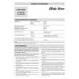
Mounting
1. Attach the fall prevention wire to the
camera, followed by attaching it to the ceiling slab (Fall prevention wire is not included.) Connect the video signal cable. (A pg. 14) Lower the cover and connect the connectors. Upon connecting, cover the connectors using the protection cover. (A pg. 15) Install the Ferrite core (TK-C210FW only) (A pg. 14) Connect the alarm cable. (TK-C215V12 only) (A pg. 15) Wrap insulation tape around cables. Insert the camera unit into the ceiling hole.
1. Align j with the shooting direction when
mounting the camera.
2.
2. Fasten the camera. (x3 locations)
A Press the screw head of the clamping bracket
all the way in using a cross screwdriver.
B With the screw pressed in using the
screwdriver, turn about 90 in the clockwise direction, followed by pulling out the screwdriver.
3. Connect the input power supply cable. 4. 5. 6. 7.
C The clamping bracket is attached to the ceiling
and the camera fastened.
NOTE:
Dismantle the camera upon turning the screw heads of the ceiling mount bracket (x3) by 90 in the anti-clockwise direction.
7.
Fall prevention wire (not supplied) Protection cover
Alarm signal cable (TK-C215V12 only)
3.5. or crimp Solder
2.
Insulation tape
1.
6.
Wrap with tape
1.
F U RO P NT
Input power supply cable
B A
Align with shooting direction
2.
*TK-C215V4 is used in the above illustration
Adjusting Images
*TK-C215V12 is used in the above illustration
After mounting is completed, adjust the images while checking the actual image. (A pg. 23 AAdjusting ImagesB)