|
|
|
Who's Online
There currently are 5876 guests and
2 members online. |
|
Categories
|
|
Information
|
|
Featured Product
|
|
|
 |
|
|
There are currently no product reviews.
 ;
I needed the manual immediately and I got it immediately. I couldn't find this manual anywhere else on the net. The site was easy to traverse, and the price was very reasonable. I'll definitely be back for any future needs.
 ;
I received a good service manual, with good resolution. Improve the instructions for the purchase because they are not well understood.
For the rest, so good.
Thanks Angel.
;
Very good documentation for the Grundig 2077 model (as well as similar 800/900/1000 series radios). The first two pages are a summary of reception specifications and output capability. The third page is the tuner dial indicator and dial cord routing diagram. the final ~5 pages are the schematics for the various models (including 2077). The scan quality of the schematics are good, adn can be easily read if zoomed in. The documents are in German, not English as stated. It would have been nice to have the tuning sequence and settings, and some trouble shooting materials... or component and wiring map.
;
Perfect like it was descriped, Perfect like it was descriped
;
Very good detail, all pages clear, exactly what I needed
UX-L46V/UX-L36V
Removing the Main board/ the Heat sink board (See Fig.11~13)
Remove the metal cover, the rear cover and the rear panel. 1. Disconnect the card wire from connector CN902, CN903, CN904 and CN905 on the main board and remove the CD-R/RW mechanism assembly. REFERENCE: Refer to the method of removing the CD-R/RW mechanism assembly and Fig.8. 2. Disconnect the vocal board from connector CN920 on the main board. REFERENCE: The vocal board can be detached without removing the main board. 3. Remove the two screws I attaching the main board. 4. Disconnect the card wire from connector CN931, CN935, CN933, CN934, CN913, CN901, CN900 and CN917 on the main board. 5. Remove the band f and disconnect the card wire from connector CN951 on the power transformer assembly. Remove the main board / the heat sink board from the body. 6. Release the joint e of the main board and disconnect connector CN944 and CN945 of the heat sink board from connector CN915 and CN916 of the main board respectively. 7. Remove the two screws J attaching the heat sink bracket and heat sink board. Fig.12
Main board Heat sink CN915 CN916 Main board Optical digital board CN905 CD-R/RW mechanism assembly
CN902 CN904 CN903
e
I
I
Fig.11
Main board CN920
Vocal board
Main board Heat sink
CN933
CN931 CN935
J
CN934 CN900 CN913
CN917 CN901
f
CN951 Power transformer assembly
CN945 CN944
Heat sink board
Fig.14
Fig.13
1-8
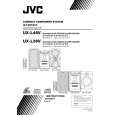 $4.99 UX-L36V JVC
Owner's Manual Complete owner's manual in digital format. The manual will be available for download as PDF file aft…
|
|
|
> |
|