|
|
|
Who's Online
There currently are 6043 guests online. |
|
Categories
|
|
Information
|
|
Featured Product
|
|
|
 |
|
|
There are currently no product reviews.
 ;
5 STARS for FAST DELIVERY, BEST PRICES and QUALITY PRODUCT. Item was exactly as described with superb resolution. Will definitely source all my future requirements from this website. Thanks a lot owner-manual.com!
;
OEM manual provided all schematics, board layouts and component specs necessary to facilitate unit maintenance. All pages were clear and readable.
;
Good condition and quality. Hard to find anywhere in Internet, only on this site.
 ;
Exactly what I needed to be able to bring the amp back to life... will come back to this site the next time I need schematics.
;
Information was accurate and very helpful.
However the continuity made it a little difficult to follow from one page to the next.
UX-M5R
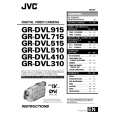
Removing the power board (See Figs. 16 and 17.)
Remove the left and right side panels. 1. Disconnect the wires from the connector CN901 on the power board. 2. Remove the tie bands bundling the wires. 3. Remove the screw M retaining the lug wire. 4. Remove the two screws N retaining the chassis . 5. Remove the power board by pinching the two studs retaining the power board using radio pliers, etc.
Chassis Lug wire Main board
Power transformer
Stud
CN901 Stud Tie bands
N
Fig.16
M
Power board
Radio pliers, etc.
Power board Stud
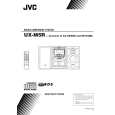
Removing the main board (See Figs. 18 and 19.)
Fig.17 Remove the left and right side panels. Remove the top cover. Remove the front panel assembly. Remove the CD mechanism assembly. 1. From the inside of the rear panel, remove the five screws P retaining the bracket. 2. Remove the two screws Q retaining the speaker terminal of the main board. 3. Remove the solder from the soldered part e that attaches the FM antenna wire to the antenna board. 4. Remove the three screws R retaining the rear panel, then remove the rear panel. 5. From the top side of the main body, remove the screw S retaining the bracket of the main board. 6. Remove the screw T retaining the regulator IC(IC302). 7. Remove the tie bands bundling the wires. 8. Disconnect the wire from the connector CN901 on the power board. 9. Remove the stud on the main board, and then take out the main board from the chassis.
Soldered part e Heat sink
Chassis
P
P
R Q
Fig.18
R
Regulator IC Main board FM antenna wire (IC302) Antenna board T Stud
CN901
S
Power board Bracket Power transformer Tie bands
Chassis
Fig.19
1-10
 $4.99 UX-M5R JVC
Owner's Manual Complete owner's manual in digital format. The manual will be available for download as PDF file aft…
|
|
|
> |
|