|
|
|
Who's Online
There currently are 5809 guests online. |
|
Categories
|
|
Information
|
|
Featured Product
|
|
|
 |
|
|
There are currently no product reviews.
 ;
Incredibly clear!!!! Well done, complete and wonderful. It could not better than this!!!!
 ;
Thank You for fast delivery for the sheme.
Everything allright.
Thanks & best regards Franz
;
again you did a very good job. It was fast too. Photocopy are really readable and clear
;
Probably it never existed a 1081 official service manual from Commodore, it's look more like a NAPCEC service manual & diagrams compilation of the 1084 series and his variants, like the nap6523, 8cm505, 1084S, 1084P and obviously the 1081. It's more complete than other scans and the quality of the scans also are far superior. It has two circuit diagrams variants of the 1081, mono and stereo versions. It doesn't include a diagram for the Philips CM8500 or CM8501, they look like the 1081 but they are slightly different.
;
Rapid, clear well done as all the scheme I downloaded from this site. Great job very functional and very useful
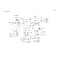
UX-V10GN
<Front panel assembly>
Prior to performing the following procedure, remove the rear cover, the side panels, the cassette mechanism assembly, the main board and the front panel assembly.
M
CD mechanism cover (CD mechanism assembly)
Removing the CD mechanism assembly (See Fig.18 to 21)
1. Disconnect the harness from connector CN721 and CN722, and the card wire from CN766 on the LCD board on the back of the front panel assembly.
CN766
R M
Belt Loading motor
M
CN721 LCD board CN722
2. Remove the five screws M attaching the CD mechanism cover to the front panel. Remove the CD mechanism cover together with the CD mechanism assembly. 3. Release the harness from each hook on the CD mechanism cover. 4. Remove the five screws N attaching the CD mechanism cover and the CD mechanism case. Release the three joints g of the CD mechanism cover and the CD mechanism case by pushing the joint hooks inward. 5. Disconnect the card wire from connector CN603 and the harness from CN605 on the CD servo control board. 6. Remove the CD mechanism assembly from the CD mechanism cover by pulling out it from the three bosses h.
Joint g
Fig.18
N
Joint g
N
CD mechanism cover
Loading motor CD mechanism case
N
Joint g
Removing the LED board (A) (See Fig.21)
1. Remove the screw O attaching the LED board (A).
N
Fig.19
CD mechanism cover
CD servo control board
LCD board (A) CD mechanism case Joint g CN603 CN605 CD mechanism cover
Fig.21
Fig.20
1-10
 $4.99 UX-V10 JVC
Circuit Diagrams Set of circuit diagrams. The diagrams will be provided as PDF file. The file will be delivered after…  $4.99 UXV10 JVC
Owner's Manual Complete owner's manual in digital format. The manual will be available for download as PDF file aft…  $4.99 UX-V10 JVC
Parts Catalog Parts Catalog only. It's available in PDF format. Useful, if Your equipment is broken and You need t…
|
|
|
> |
|