|
|
|
Who's Online
There currently are 6043 guests online. |
|
Categories
|
|
Information
|
|
Featured Product
|
|
|
 |
|
|
There are currently no product reviews.
 ;
Hard to find manual was ready the next day. Scans were very legible (including schematics). All the essential parts of the service manual were present (adjustment procedure, schematics, and parts list). It would have been nice if the rest of the manual was included (disassembly procedure, theory of operation, etc.).
 ;
The Service Manual for the Kenwood KR-V55R provided by owner-manuals.com was as described/advertised. The contents provided the necessary information to effect a diagnosis of the unit. The schematics above all else was instrumental in tracing the the signal flow from component to component.
;
This manual was the factory original. Excellent value and contained all the details I needed. Easy dowwnload provided the information when I needed it.
;
Impeccable, document très complet. Perfect, i get all i need. All schematic are correct. Thanks
;
The manual is of better quality compared to other. I found it less expensive and therefore it it is the best buy cost vs quality.
VS-DT68V
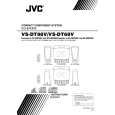
Attaching the pickup unit (See Figs. 6 to 8.)
[Reference] Refer to the explanation of "Removing the pickup unit" on the preceding page. 1. Attach the P.S. spring and rack to the pickup unit. (See Fig.6.) 2. Insert the C.D shaft into the pickup unit. (See Fig.6.) 3. Engage the section f of the pickup unit with the traverse mechanism assembly first, and set the both ends of the C.D shaft in the grooves g and h. (See Fig.7.) 4. After making sure that the section j of the rack is meshed correctly with the middle gear, attach the C.D shaft using the two screws F. (See Fig.8.)
Groove g
Section f
Groove h
Fig.7
Section j
F
Rack
Fig.8
Removing the traverse mechanism board (See Fig. 9.)
Remove the CD servo board and video board. Remove the traverse mechanism assembly. 1. From the back side of the traverse mechanism assembly, disconnect the spindle motor wires and feed motor wires that are soldered on the traverse mechanism board. 2. Remove the two screws J attaching the traverse mechanism board.
J
Traverse mechanism assembly
Spindle motor Black Red Red Traverse mechanism board
K
Feed motor
J
Removing the feed motor (See Fig. 9.)
Remove the CD servo board and video board. Remove the traverse mechanism assembly. 1. From the back side of the traverse mechanism assembly, disconnect the feed motor wires that are soldered on the traverse mechanism board. 2. Remove the two screws K attaching the feed motor.
Fig.9
1-13
 $4.99 VS-DT68V JVC
Owner's Manual Complete owner's manual in digital format. The manual will be available for download as PDF file aft…
|
|
|
> |
|