|
|
|
Who's Online
There currently are 5998 guests and
1 member online. |
|
Categories
|
|
Information
|
|
Featured Product
|
|
|
 |
|
|
There are currently no product reviews.
 ;
This PDF is very comprehensive. It includes drawings, parts lists, schematics, pictures, PCB drawings, mechanical layouts, etc. for all three stackable equipment. The scans are good too. Easy to read and no smudges or black lines. I have no complaints. I will make this site my first stop for finding my service manuals.
 ;
This service manual includes drawings, schematics, exploded views, parts list, operating details, and more. Very good scans, very readable. The only thing that made it a 4 star rating was on approximately 4 scans only half of the page was scanned then the other half. I would have preferred the pages to be whole scans.
;
Good manual contains all it takes to update, repair,these types of mixers.Thanks.
;
Great service. Fast response. High quality scan. Good price.
Thank you very much!!!
Oleg S.
;
Well-scanned, complete manual. Contains the information needed for repair and maintenance.
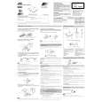
XM-PX5SL Removing the chassis ass�y (See Fig.5 and 6)
1. Remove the two screws B and the one screw C attaching the chassis assy. Remove the one screw D attaching the jack cover. 2. Open the battery lid and release the tab d from the battery contact. Pull out the battery lid. 3. Remove the one screw E attaching the arm (L). 4. Remove the chassis ass�y and the arm (L) while releasing them from the headphone jack on the bottom case.
Battery lid
B
Chassis ass'y
B
Bottom case
D C
Headphone jack Jack cover
Removing the main P.W. board and the battery holder(See Fig.7 and 8)
1. Use a soldering bit provided with ground to solder or unsolder the short round.
Fig.5
Headphone jack
2. Ground the set and the P.W.board. The voltage level of the ground should be equal to that of the soldering bit. 3. Prevent static electricity using an earth band, etc. 4. Solder the short round of the pickup FRC for short circuit. 5. Disconnect the flexible wires from the connector CN301 and CN801 on the main P.W.Board.
d Arm (L)
E
6. Remove the one screw F attaching the main P.W.board. Remove the main P.W.board and the battery holder, then reverse them. 7. Disconnect the flexible wire from connector CN601 on the main P.W.board.
Battery holder Soldering
Fig.6
8. Unsolder the soldered joint of the main P.W.board and the battery holder P.W.board.
Battery holder MD mechanism ass'y
F
CN401
Pickup short round CN601 Main P.W.board
CN301 Main P.W.board
Fig.8
Fig.7
1-6
 $4.99 XMPX5SL JVC
Owner's Manual Complete owner's manual in digital format. The manual will be available for download as PDF file aft…
|
|
|
> |
|